


Pressures to 400 psi (28 bar)
Port sizes:2" and 2-1/2" SAE split flange
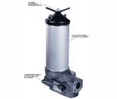
The 8384/85 series filter assemblies are no longer available and are being replaced with Ultipleat® UR649 Filter Assemblies
All replacement filter elements, differential pressure indicators and sealkits remain available for this series. See 'Ordering Information' tab above for details of spares.
Features
- Optional Differential Pressure Device
- Changeover Handle with Latching Pin Mechanism
- 8310 or 8314 Series (Ultipor® III Element)
Maximum Acceptable Working Pressure:
400 psig (28 bar)Fatigue Pressure Rating:
330 psig (23 bar)(107 cycles per NFPA T2.6.1-1974)
Typical Burst Pressure:
2100 psig (145 bar)Temperature Range:
Nitrile seals -45°F to 225°F (-43°C to 107°C)Fluorocarbon seals -20°F to 250°F (-29°C to 120°C) 140°F (60°C) maximum in HWCF or water-glycol fluids
Filter Element Collapse Pressure:
8314–150 psid (10 bar)8310–100 psid (7 bar)
Materials of Construction:
Head, cover, handle, tube, manifold and valve bodies – aluminum alloy. Center post, core, and internal valve parts – coated carbon steel.
Housing Pressure drop is directly proportional to specific gravity.
Element Pressure Drop Factor
Multiply actual flow rate times factor to determine pressure drop with fluid at 150 SUS (32 cSt), 0.9 S.G.Correct for other viscosities by multiplying new viscosity in SUS/150 x new S.G/0.9.
| 8310/14 Series Element | |||||
| Length | KZ | KP | KN | KS | KT |
|---|---|---|---|---|---|
| 16" | 0.089 | 0.047 | 0.040 | 0.031 | 0.022 |
| 39" | 0.034 | 0.018 | 0.015 | 0.012 | 0.008 |
 P factor (psid/gpm)
| Assembly P/N: | H |
| 838 |
| D |
|
|
|
|
|
|
|
|
|
|
| Table1 |
| Table2 | Table3 | | Table5 | Table6 | Table7 | Table8 | Table9 |

| Element P/N: | HC 831 |
| F |
|
|
|
|
|
|
|
|
|
| Table4 | Table5 | Table6 | Table1 |
|
|
|
Note:Choose from the options in the following tables to compile the specific Product Number.
| Table 1: Seal Options | |
| Code | Seals |
|---|---|
| H | Buna N |
| Z | Fluorocarbon |
| Table 2: Housing Series Options | |
| Code | Element |
|---|---|
| 4 | Coreless (use Code '4' in table 4) |
| 5 | Standard (use Code '0' in table 4) |
| Table 3: Port Size Options | |
| Code | Size |
|---|---|
| 32 | 2" SAE flange |
| 40 | 2-1/2" SAE flange |
| Table 4: Element Series Options | |
| Code | Options |
|---|---|
| 4 | 8314 series coreless filter elements |
| 0 | 8310 series filter elements (with core) |
| Table 5: Filter Element Options | ||
| Code | ßx | ßx(c)=1000 |
|---|---|---|
| KZ | <1 | 2.5 |
| KP | 3 | 5 |
| KN | 6 | 7 |
| KS | 12 | 12 |
| KT | 25 | 22 |
 200
200| Table 6: Length Options* | ||
| Assembly Code | Element Code** | Dry Weight Maximum |
|---|---|---|
| U | 16 | 61 lb. |
| X | 39 | 82 lb. |
* Use code in second column for element part no. | ||
| Table 7: Bypass Valve Options | ||
| Code | Description | |
|---|---|---|
| A | 25 psid ± 3 psid bypass | |
| B | 50 ± 5 psid bypass | |
| Y | Without bypass* 16 psid  P indicator P indicator | |
| N | Without bypass* 35 psid P indicator | |
| 1 | Without bypass* with P device F or B | |
*Caution: If non-bypass configuration is selected, do not use in systems with surge pressures over 90 psig (8385) or 120 psig (8384), in order to avoid possible filter element collapse and containment passing downstream.
| Table 8: Differential Pressure Device Options | ||
| Code | Description | Location |
|---|---|---|
| B | Plug in place of P device | Both |
| P | Visual indicator with thermal lockout | Cover |
| D | 'P' type with no thermal lockout | Cover |
| L | Electrical switch (SPDT) with 6" leads | Base |
| S | Electrical switch with MS receptacle | Base |
| T | 'L' type with DIN connector | Base |
| M | 'T' type with wiring cap | Base |
| 2 | 'P' and 'L' | As above |
| 3 | 'P' and 'S' | As above |
| Table 9: Handle Orientation Options | ||
| Code | Handle Orientation | |
|---|---|---|
| L | Handle on left side when facing inlet port | |
| R | Handle on right side when facing inlet port | |
Earn 10% off* your next order online by leaving a review of this product. Please login to your account to leave a review. We appreciate and value your feedback.
*Subject to Terms and Conditions.