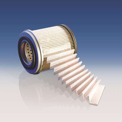
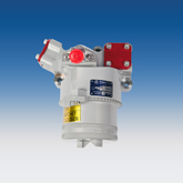
A laid-over pleat geometry which offers improved performance and a reduction in filtration operating costs.
- Longer filter element service life
- Up to 50% smaller and lighter
- OEM approved
Why do Ultipleat elements have lower operating costs?
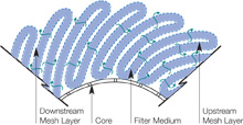
Long Service LifeThe unique, laid-over pleat geometry provides a greater filtration area than conventional ‘fan-pleat’ filter elements for the same envelope. This, coupled with a more uniform flow distribution results in a significant increase in dirt holding capacity when compared to a fan (radial) pleat construction in the same space envelope.
Side by side comparison testing has shown
Up to 50% more dirt capacity for Ultipleat compared to conventional fan pleat
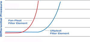
Alternatively, the larger filtration area can be used to design an Ultipleat filter element with a finer micron rating and the same service life compared to a fan-pleat design in the same space envelope.
Low weight and space requirements
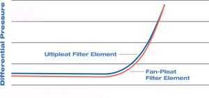
Ultipleat elements have a lower flow density, and consequently, a higher flow capacity. As a result, filter size can be reduced substantially. The smaller size combined with polymeric support meshes reduces weight by as much as 50%.
The higher dirt capacity(service life) for the same envelope can be traded off for a smaller envelope with the same dirt capacity as the conventional radial pleat filter element. In addition, the use of polymeric support meshes can also lead to a substantial reduction in filter element weight.
A low average pressure drop is important for keeping energy consumption to a minimum. This allows more flow through the filter during low temperature, high viscosity start-up conditions.
Stability of performanceThe pleats are supported both upstream and downstream which helps to maintain efficiency and performance during cyclic flow or cyclic pressure(pump ripple) conditions.
Why do Ultipleat elements have a uniform flow distribution?
 |
 |
|
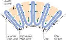
Conventional pleated filter element construction, showing Non-uniform flow distribution (Outside to Inside flow direction).In a conventional filter element the pleats radiate outward from the core and the spacing between the pleats increases. This space represents wasted volume and unused filtration area. |
Ultipleat filter element construction showing uniform flow distribution (Outside to Inside flow direction).
|
Why do some engines use a reverse-flow filter element?
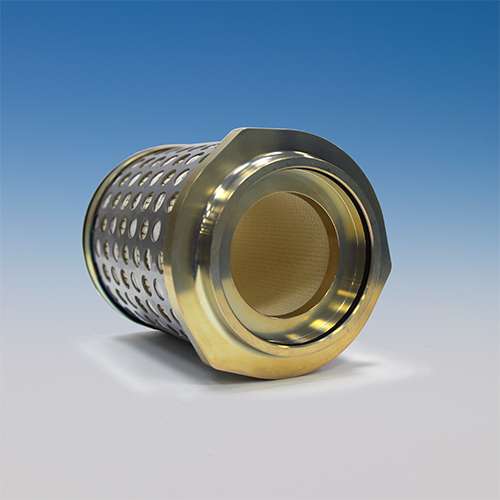
In a reverse-flow Ultipleat design, the fluid flows from Inside to Outside and all the contaminants are retained inside the filter element. This concept offers several benefits:
- Weight saving - structural core can be integrated into the filter bowl
- Simpler maintenance - no need to clean filter bowl
- Less chance of cross-contamination during filter element change out
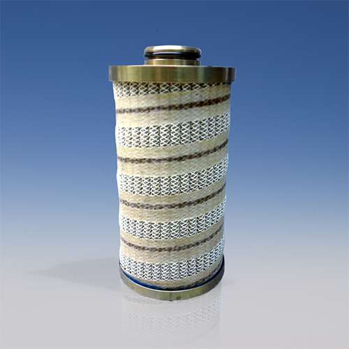
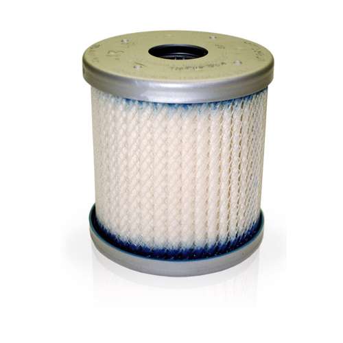
- Engine Lube
- Engine Fuel
- Hydraulic
- Helicopter Transmissions
- Liquid Cooling
 |
 |
 |
Literature and Other Resources
Aerospace Ultipleat Data sheet
Optimizing Filter Element Design for Size, Weight and Life Improvements, Paper No. IFC10-002
Our filter elements are designed and tailored to meet the customer specification requirements.
If you have an aerospace application that needs an Ultipleat laid-over pleat design, please talk to one of our experts Contact Aerospace
For commercial aircraft products, please contact our authorised distributor, Satair
We appreciate your review of this product. Please login to your account to leave a review.


