


Datasheets
Download:The CPF Process Reduces Downtime
All Fluid Dynamics CPF Systems, both Model 100 and 200 series operate using parallel filter circuits that permit continuous, uninterrupted process filtration.
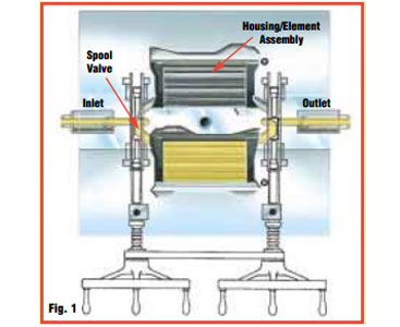
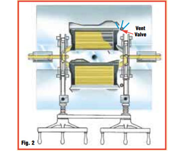
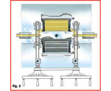
In operation, one filter housing/element assembly is on-stream until a predetermined differential pressure is reached(Fig. 1). Then, by operating the two handwheels, the spool valves are repositioned, in proper sequence, to progressively close off flow to the housing containing the “dirty” filter elements, and divert flow to the off-stream housing containing the clean filter elements (Fig. 2). Vent valves are incorporated to purge the air during the filling of the off-stream housing to maintain balanced system pressure and prevent entrainment of air in the process stream. Upon completion of the changeover sequence (Fig. 3), the “dirty” housing/element assembly is removed and replaced with a clean assembly.
The CPF Advantage Simple and Field-Serviceable
Our CPF systems are designed for ease of operation and maintenance, and they eliminate the need for breaking heating connections and disassembling interconnecting piping during CPF filter housing changes. As a result, CPF housing changes can be completed in less than 30 minutes. Furthermore, all components in our CPF systems are field serviceable by trained technicians.
Custom systems may be designed for specific applications requiring enhanced flow properties.
All CPF systems are designed to offer safe, dependable and uniform heating.
Model 100 Series CPF Systems
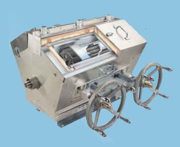
Our CPF Model 100 series are standard horizontal systems with a compact design, ideal for applications with low flow rates and/or limited space. The valves are operated manually and can provide a smooth, “bumpless” changeover, with no disruption to the down-stream process.
Model 200 Series CPF Systems
Our CPF Model 200 series are large, vertical systems designed for applications with special requirements and/or high flow rates. They are available configured for manual operation, or in fully automated, computer-controlled designs. With the complete computer-controlled valve package, the Model 200 ensures consistently smooth, “bumpless” changeovers, and significantly reduces operator error and safety risks
In Model 200 CPF systems, the filter housing and heat exchanger together form a simple, self-aligning mechanism that enables the removal and installation of the filter housing in less than 30 minutes.
Model 100 Series CPF Systems
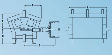
MODEL 100 DIMENSIONS (mm)
| 110 | 120 | 130 | 135 | 140 | |
| A | 324 | 334 | 324 | 324 | 508 |
| B | 339 | 345 | 355 | 355 | 424 |
| C | 362 | 381 | 381 | 381 | 546 |
| D | 635 | 762 | 762 | 762 | 775 |
| E | 356 | 356 | 356 | 356 | 356 |
| F | 610 | 826 | 826 | 1207 | 1092 |
Design Criteria
| System Pressure: | to 345 bar |
| System Temperature: | to 330˚ C |
| Differential Pressure: | to 210 bar depending on element configuration |
| Heating: | liquid, vapor or electric |
Connections
| Process: | Butt weld standard. Clamp or flange style available |
| Heating: | Butt weld standard. Flange style available |
Materials of Construction
| Valve Bodies: | Type 304 stainless steel |
| Filter Housings: | Type 17-4 PH stainless steel |
| Seats & Gaskets: | Aluminum |
| Packings: | RYTON® standard (others available) |
| Heat Exchanger: | Carbon steel, double wall construction (liquid or vapor) Aluminum (electric) |
| Insulation: | High temperature fiberglass blanket with non-stick outer covering standard (stainless steel cover available) |
Model 200 Series CPF Systems
Design Criteria
| System Pressure: | to 345 bar |
| System Temperature: | : to 330˚C |
| Differential Pressure: | to 210 bar depending on element configuration |
| Heating: | liquid, vapor or electric |
Connections
| Process: | Butt weld standard Clamp or flange style available |
| Heating: | Butt weld standard Flange style available Complete heating manifolds available |
Materials of Construction
| Valve Bodies: | Type 17-4 or 304 stainless steel |
| Filter Housings: | Type 17-4 or 304 stainless steel |
| Seats: | Aluminum |
| Housing Seals: | Stainless steel o-ring |
| Packings: | Ryton standard (others available) |
| Heat Exchanger: | Carbon steel, double wall construction (liquid or vapor) aluminum (electric) |
| Insulation: (option) | High temperature fiberglass blanket with non-stick outer covering stainless steel cover available |
The heat exchanger and the filter housings are designed to ASME code and may be "U" stamped upon request.
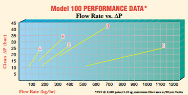
Model 100 CPFs
| System | Filter Area | Valve Bore | |
| A | 110 | 0.5 m2 | 27 mm |
| B | 120 | 1.1 m2 | 27 mm |
| C | 130 | 1.1 m2 | 38 mm |
| D | 135 | 2.2 m2 | 38 mm |
| E | 140 | 3.5 m2 | 58 mm |
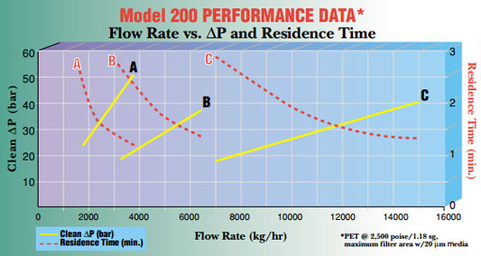
Model 200 CPFs
| System | Filter Area | Valve Bore | |
| A | 230 - 10940 | 11.5 m2 | 58 mm |
| B | 240 - 13250 | 20.0 m2 | 80 mm |
| C | 250 - 18756 | 45.0 m2 | 103 mm |
We appreciate your review of this product. Please login to your account to leave a review.