


Documents
Datasheets
Download:Description
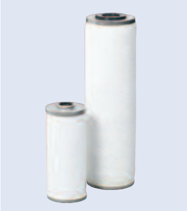
Small Flow Gas Coalescing Assembly
Small Flow Gas (SFG) Coalescing Assemblies are rugged, inexpensive, high efficiency assemblies that eliminate problems caused by oil, water, and dirt in air or gas
Performance Specifications
- Removal of 99.99% of all aerosols 0.3 microns and larger. Typical downstream aerosol concentrations are less than 0.003 ppm.
- Patented surface treatment that prevents liquids from wetting the coalescer media allowing for higher gas flow capacity and lowered fouling tendency and differential pressure.
- Consistent performance using thin fibers and fixed pore construction optimized for efficient coalescing.
- Long service life due to pleated media structure and surface treatment.
- Low energy losses with typical saturated pressure drop of 1.2 psid (82.7 mbard).
- Wide range of compatibility for use with process gases, compressor oils, hydrocarbon condensates, and water
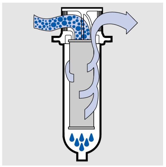
Inside to Out Flow Pattern of SFG Coalescer Assembly
SFG Coalescer Features
Positive Seal: Standard seal material is Nitrile (H13) available as either an internal o-ring or flat gasket depending on coalescer size.
Outer Drainage Layer: Drainage of coalesced liquid and protection from re-entrainment is provided by a polymeric outer drainage layer. This ensures consistent, high efficiency performance.
Metal Support Core: Axial strength and protection against liquid slugs are provided by a perforated inner support core constructed of 304 stainless steel.
Outer Cage: Media support during operation is provided by a 304 stainless steel outer support cage.
Primary Coalescer: Coalescing is achieved by use of a high area pleated glass fiber medium that is surrounded by a non-woven polymeric support and drainage layers. A patented surface treatment is used that enhances coalescer performance and lowers fouling tendency and pressure drop.
End Caps: 304 stainless steel end caps are used to improve cartridge strength and prevent contaminant bypass.
Key Benefits
- Protects process analyzers
- Safeguards instrument air operated equipment and systems
- Prevents orifice plugging in pneumatic controllers
- Improves accuracy of gas measurements in the field or plant
- Decreases freeze-out and corrosion problems
- Reduces fouling in small gas-driven engines
- Provides reproducible high-quality gas for all operations using produced gas
Specifications
SFG Coalescer Element Specifications
| Coalescer Part Number1 | PFS4463ZMH13 | PFS1001ZMH13 |
| Coalescing Efficiency at 0.3 μm | 99.99% | 99.99% |
| Rated Flow Air @ 100 psig (6.9 bard) and 100°F (38°C) | 60 scfm (8.3 acfm) | 200 scfm (27.6 acfm) |
| Effective Coalescer Area | 0.84 ft2 (0.078 m2) | 2.2 ft2 (0.204 m2) |
| Clean Saturated Pressure Drop | 0.53 psid (36.54 mbard) | 1.5 psid (103.4 mbard) |
| Maximum Temperature (water present) | 140°F (60°C) | 140°F (60°C) |
| Maximum Temperature (no water) | 250°F (121°C) | 250°F (121°C) |
| Maximum Differential Pressure2 | 50 psid (3.4 bard) | 50 psid (3.4 bard) |
| Dimensions: | 21/4 in O.D. x 51/4 in (57.2 mm O.D. x 133.4 mm) |
23/4 in O.D. x 93/4 in (69.9 mm O.D. x 247.7 mm) |
| Sealing Mechanism | Single open-ended with internal o-ring | Double open-ended with gaskets / tie rod |
1 Standard seal material is Nitrile (H13). Fluorocarbon Elastomer (H) and Ethylene Propylene (J) are also available for optimum fluid compatibility.
2 A change out differential pressure of 15 psid is recommended to ensure efficient operation.
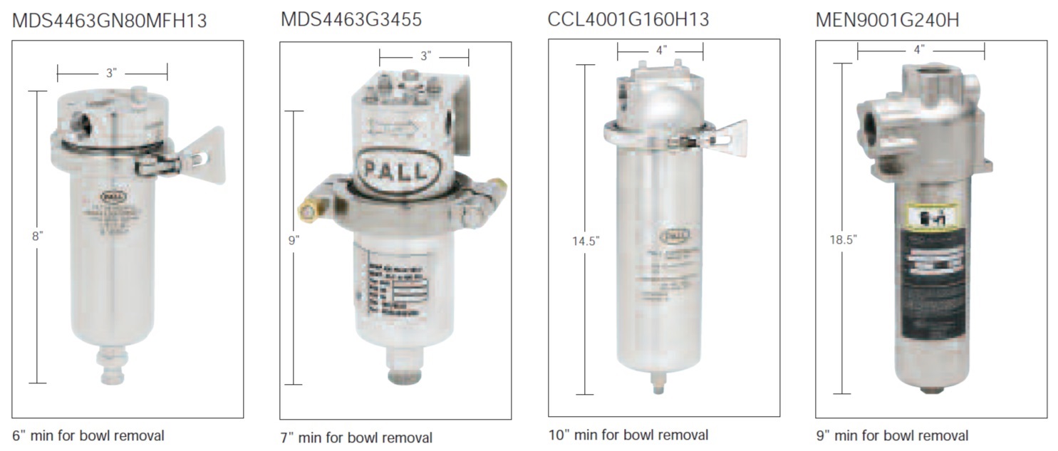
SFG Coalescer Housing Specifications
| SFG Housing Part Number |
Housing Materials of Construction |
Replacement Cartridge | Design Pressure (psi/bar) |
Number of Cartridge | Weight (lb/kg) Dry |
Weight (lb/kg) Weight |
Connection & Drain Sizes (NPT) (in/mm) |
| MDS4463GN80MFH13 | 316 SS | PFS4463ZMH13 | 150/10.3 | 1 | 3.6/1.7 | 5.7/2.6 | 0.5/12.7 |
| MDS4463G3455 | 316 SS | PFS4463ZMH13 | 400/27.6 | 1 | 15.0/6.8 | 22.0/10.0 | 0.5/12.7 |
| CCL4001G160H13 | 316 SS | PFS1001ZMH13 | 400/27.6 | 1 | 7.0/3.2 | 13.0/5.9 | 1.0/25.4 |
| MEN9001G240H | Nickel Plated Carbon Steel | PFS1001ZMH13 | 4000/275.8 | 1 | 26.0/11.8 | 32.0/14.5 | 1.5/38.1 |
Performance
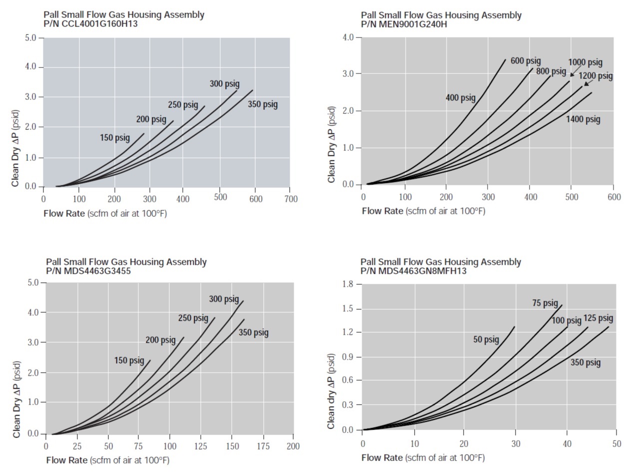
To calculate the pressure drop for other process conditions use the following equation:
P = KH QA2 ρ + KC QA μ
where :
P: pressure drop in psid
KH: housing pressure drop constant
QA: actual flow rate in acfm
ρ: gas density at operating conditions in lb/ft3
KC: coalescer pressure drop constant
μ: gas viscosity at operating conditions in cP
Type
Ordering Information
| Coalescer Assembly P/N | KH | KC |
| CCL4001G160H13 | 0.00267 | 0.2703 |
| MEN9001G240H | 0.00973 | 0.2703 |
| MDS4463G3455 | 0.04346 | 0.6864 |
| MDS4463GN8MFH13 | 0.07000 | 0.6864 |
Reviews
We appreciate your review of this product. Please login to your account to leave a review.