


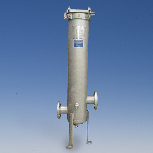
IML Series Filter Housings
Datasheets
Download:- Multi-cartridge housing accepts 3-7 AB-style, Single Open End, Double Open End, RF, and 1001-style filters, depending upon model selected
- Accepts 10 in. (254 mm), 20 in. (508 mm), 30 in. (762 mm), or 40 in. (1016 mm) Pall Code 3, Code 7, Code 8, Code 18, 1001, DOE, or RF filter cartridges
- All wetted parts are 316 stainless steel
- Offset T connections for easy installation
- Quick-opening swing bolt closure facilitates filter change-out
- Wide choice of inlet/outlet sizes and O-ring seal materials
- Options for passivation and cleaning for oxygen service
Maximum Allowable Working Pressure
- 195 psig (13.44 bar) @375 °F (190.6 °C)
- 210 psig (14.48 bar) @300 °F (148.9 °C)
- 230 psig (15.86 bar) @200 °F (93.3 °C)
- 260 psig (17.93 bar) @100 °F (37.8 °C)
Materials of Construction
- Head and Body: 316/316L Stainless Steel
- Code: ASME Code, Section VIII, Division I U stamp
Connections
- Inlet/Outlet: 2-3" NPT, 2-4" 150lb. ANSI Raised Face Flange
- Vent/Drain: 1/2" NPT Vent; 1" NPT Drain
- Gauge Ports: 1/4" NPT
- Shell O-rings1: Fluorocarbon, FEP Encapsulated Fluorocarbon, Silicone, Nitrile, Ethylene Propylene, Ethylene Propylene for Steam Service
Housing Differential Pressure vs. Liquid Flow Rate

Housing Differential Pressure vs. Air Flow Rate

Dimensional Data
| Model | Flow Rate2 | Dimensions A (in/mm) Max. | Volume (ft3) | Weight (empty) (lbs/kg) | Weight Full (water) (lbs/kg) |
| IMLA131 | 10/37.9 | 37/939.8 | 0.7532/0.0213 | 137/62.14 | 184/83.46 |
| IMLA132 | 20/76 | 47/1193.8 | 1.0577/0.03 | 146/66.22 | 212/96.16 |
| IMLA133 | 30/114 | 58/1473.2 | 1.3622/0.0386 | 155/70.31 | 240/108.86 |
| IMLA134 | 40/151 | 68/1727.2 | 1.6667/0.0472 | 166/75.30 | 270/122.47 |
| IMLAD31 | 10/37.9 | 37/939.8 | 0.7532/0.0213 | 137/62.14 | 184/83.46 |
| IMLAD32 | 20/76 | 47/1193.8 | 1.0577/0.03 | 146/66.22 | 212/96.16 |
| IMLAD33 | 30/114 | 58/1473.2 | 1.3622/0.0386 | 155/70.31 | 240/108.86 |
| IMLAD34 | 40/151 | 68/1727.2 | 1.6667/0.0472 | 166/75.30 | 270/122.47 |
| IMLA731 | 10/37.9 | 37/939.8 | 0.7532/0.0213 | 137/62.14 | 184/83.46 |
| IMLA732 | 20/76 | 47/1193.8 | 1.0577/0.03 | 146/66.22 | 212/96.16 |
| IMLA733 | 30/114 | 58/1473.2 | 1.3622/0.0386 | 155/70.31 | 240/108.86 |
| IMLA734 | 40/151 | 68/1727.2 | 1.6667/0.0472 | 166/75.30 | 270/122.47 |
| IMLA831 | 10/37.9 | 37/939.8 | 0.7532/0.0213 | 137/62.14 | 184/83.46 |
| IMLA832 | 20/76 | 47/1193.8 | 1.0577/0.03 | 146/66.22 | 212/96.16 |
| IMLA833 | 30/114 | 58/1473.2 | 1.3622/0.0386 | 155/70.31 | 240/108.86 |
| IMLA834 | 40/151 | 68/1727.2 | 1.6667/0.0472 | 166/75.30 | 270/122.47 |
| IMLAT31 | 10/37.9 | 37/939.8 | 0.7532/0.0213 | 137/62.14 | 184/83.46 |
| IMLAT32 | 20/76 | 47/1193.8 | 1.0577/0.03 | 146/66.22 | 212/96.16 |
| IMLAT33 | 30/114 | 58/1473.2 | 1.3622/0.0386 | 155/70.31 | 240/108.86 |
| IMLAT34 | 40/151 | 68/1727.2 | 1.6667/0.0472 | 166/75.30 | 270/122.47 |
Dimensional Drawings

1In compliance with FDA21CFR177.2600 regulations.
2Suggested rate of flow for water. Rate varies dependent upon cartridge inlet/outlet selection.
- DI water
- Steam
- Compressed gases
- Prefilters to fermenter fee
Housings, Vessels, or Assemblies
This information is a guide to the part number structure and possible options. For availability of specific options and housing details, please contact Pall. Example Part Number: IM L A 1 7 3 GN 32 C2 H (See bold references in tables below) Part Number: IM L A < Element Style Code from Table 1 >BB < # Code from Table 2 > < Size Code from Table 3 > GN < Inlet/Outlet Code from Table4 > < Housing Code from Table 5 > < O-ring Code from Table 6 >
Material of Construction Code
L: 316/316L Stainless SteelDesign Code
A: ASME "U" StampTable 1 - Filter Element Style
| Code | Filter Element Style | Max # Around |
| 1 | 1001 | 5 |
| D | DOE / RF | 7 |
| 7 | Code 7 | 5 |
| 8 | Code 3, 8, 18 | 5-AB Style, 23⁄4 ˝ O.D. 7-M Style, 21⁄2 ˝ O.D. |
| T | Spring / Guide | 7 |
Table 2 - # Around
| Code | # Around |
| 3 | 3 Element |
| 4 | 4 Element |
| 5 | 5 Element |
| 6 | 6 Element |
| 7 | 7 Element |
Table 3 - Size
| Weight | |||||
| Code | Size | "A" | "C" | Empty (lbs/kg) | Full (Water)(lbs/kg) |
| 1 | 1 High | 37˝ | 10˝ | 137/62.14 | 184/83.46 |
| 2 | 2 High | 47˝ | 20˝ | 146/66.22 | 212/96.16 |
| 3 | 3 High | 58˝ | 30˝ | 155/70.31 | 240/108.86 |
| 4 | 4 High | 68˝ | 40˝ | 166/75.30 | 270/122.47 |
Table 4 - Inlet/Outlet
| Code | Inlet/Outlet |
| 32 | 2˝ NPT |
| 33 | 2˝ Flange |
| 48 | 3˝ NPT |
| 49 | 3˝ Flange |
| 65 | 4˝ Flange |
Table 5 - Houisng Options
| Code | Housing Options |
| None | None |
| C2 | Passivated |
| C9 | Cleaned for Oxygen Service3 |
Table 6 - O-ring Type
| Code | Column2 |
| H | Fluorocarbon Elastomer |
| H1 | FEP Encapsulated Fluorocarbon Elastomer |
| H4 | Silicone |
| H13 | Nitrile |
| J | Ethylene Propylene |
| J7 | Ethylene Propylene for Steam Service |
3Must use Code H or H1 O-Ring type.
We appreciate your review of this product. Please login to your account to leave a review.