


Pressures to 600 psi (41 bar)
Port sizes: 2" and 2-1/2"
The 8900 series filter assemblies are no longer available and are being replaced with Ultipleat® UR319 Filter Assemblies
All replacement filter elements, differential pressure indicators and sealkits remain available for this series. See 'Ordering Information' tab above for details of spares.
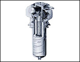
Features
- Optional Differential Pressure Devices
- Full Flow Fast Response Bypass Valve
- Easy Service Rotolok Ring
- Drawn Steel Bowl
- Optional Anti-Backflow Valve (not shown). Prevents drainage of reservoir or lines where filter is mounted below fluid level
- High Strength Fatigue Rated Housing
- Gray Cast Iron Head
- O-Ring Seals
- Ultipor® III Element
Maximum Allowable Working Pressure:
600 psi (41 bar)Fatigue Pressure Rating:
Rated Fatigue pressure: 400 psi (28 bar) 107 cycles per NFPA T2.6.1 - 1974Temperature Range:
Nitrile seals -45°F to 225°F (-43°C to 107°C)Fluorocarbon seals -20°F to 250°F (-29°C to 120°C)
140°F (60°C) maximum in HWCF or water-glycol fluids
Dry Weights:
S length– 26 lbs. (12 kg)T length– 28 lbs. (13 kg)
U length– 30 lbs. (14 kg)
Filter Element Collapse Pressure:
150 psid (10 bar)Dimensional Drawings
Element Pressure Drop Factor.
Multiply actual flow rate times factor to determine pressure drop with fluid at 150 SUS (32 cSt), 0.9 S.G.Correct for other viscosities by multiplying new viscosity in SUS/150 x new S.G/0.9.
8900 Series Element  P factor (psid/gpm) P factor (psid/gpm) | |||||
| Length | KZ | KP | KN | KS | KT |
|---|---|---|---|---|---|
| 8" | 0.30 | 0.14 | 0.12 | 0.09 | 0.06 |
| 13" | 0.19 | 0.09 | 0.07 | 0.05 | 0.04 |
| 16" | 0.14 | 0.07 | 0.05 | 0.04 | 0.03 |
| 8904 Series Element P factor (psid/gpm) | |||||
| Length | KZ | KP | KN | KS | KT |
|---|---|---|---|---|---|
| 8" | 0.36 | 0.17 | 0.14 | 0.10 | 0.07 |
| 13" | 0.21 | 0.10 | 0.08 | 0.06 | 0.04 |
| 16" | 0.15 | 0.07 | 0.06 | 0.04 | 0.03 |
| Assembly P/N: | H |
| 89 |
|
|
|
|
|
|
|
|
|
|
|
|
| Table1 |
| Table2 | Table3 | Table4 | Table5 | Table6 | Table7 | Table8 | Table9 | Table10 |

| Element P/N: | HC 8900 (8900/10 Housing) | F |
|
|
|
|
|
|
|
|
| HC 8904 (8904/14 Housing) | Table5 | Table6 | Table1 |
|
|
|
Note: Choose from the options in the following tables to compile the specific Product Number.
| Table 1: Seal Options | |
| Code | Seals |
|---|---|
| H | Nitrile |
| Z | Fluorocarbon |
| Table 2: Element/Head Options | |
| Code | Option* |
|---|---|
| 00 | 'L' (standard element) |
| 04 | 'L' (coreless element) |
| 10 | 'T' (standard element) |
| 14 | 'T' (coreless element) |
*"L" = L Head. "T" = T Head. | |
| Table 3: Port Style Options | |
| Code | Port Style |
|---|---|
| A | SAE J514 straight thread |
| B | NPT tapered pipe thread |
| D | Flange SAE J518c-code 61 |
| Table 4: Port Size Options | |
| Code | Size |
|---|---|
| 32 | 2" |
| 40* | 2-1/2" |
* D ports only. | |
| Table 5: Filter Element Options | ||
| Code | ßx | ßx(c) = 1000 |
|---|---|---|
| KZ | <1 | 2.5 |
| KP | 3 | 5 |
| KN | 6 | 7 |
| KS | 12 | 12 |
| KT | 25 | 22 |
 200
200
| Table 6: Length Options* | |
| Assembly Code | Element Code** |
|---|---|
| S | 8 |
| T | 13 |
| U | 16 |
* Use code in second column for element part no. | |
| Table 7: Bypass Valve Options | |
| Code | Description |
|---|---|
| A | 25 psid |
| B | 50 psid |
| W* | Non-bypass |
| 8* | 25 psid with ABFV |
| 9* | 50 psid with ABFV |
| V* | Non-bypass with ABFV |
* ABFV - Anti-backflow valve, available for 'T' head units only: 8910/14. | |
| Table 8: Differential Pressure Device Options | |
| Code | Description |
|---|---|
| P | Visual indicator with thermal lockout |
| D | Visual indicator with no thermal lockout |
| L | Electrical switch (SPDT) with 6" leads |
| T | Electrical switch with DIN connector |
| M | 'T' type switch with matching wiring cap |
| S | Electrical switch with MS receptacle |
| V | Combined visual/electrical with DIN connector |
| B | Bleed plug and seal in place of indicator |
| 2 | 'P' and 'L' |
| 3 | 'P' and 'S' |
| Table 9: Auxiliary Ports | |
| Code | Auxiliary Ports |
|---|---|
| N | Unmachined |
| B | Both† sides |
| R* | Right only† |
| L* | Left only† |
* Special order-contact factory. | |
| Table 10: Ejector Spring Options | |
| Code | Description |
|---|---|
| N | No ejector spring |
| S | Ejector spring |
We appreciate your review of this product. Please login to your account to leave a review.