


Pressures to 400 psi (27.5 bar)
Port sizes: 1" and 1¼"
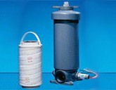
The 8924 series filter assemblies are no longer available and are being replaced with Ultipleat® UR319 Filter Assemblies
All replacement filter elements, differential pressure indicators and sealkits remain available for this series. See 'Ordering Information' tab above for details of spares.
Maximum Allowable Working Pressure:
400 psi (27.5 bar)Fatigue Pressure Rating:
Rated Fatigue pressure: 400 psi (28 bar) 107cycles per NFPA T2.6.1 - 1974Temperature Range:
Nitrile seals -45°F to 225°F (-43°C to 107°C)Fluorocarbon seals -20°F to 250°F (-29°C to 120°C)
140°F (60°C) maximum in HWCF or water-glycol fluids
Filter Element Collapse Pressure:
150 psid (10 bar)Materials of Construction:
Ductile iron head/coverSteel tube
Powder coat finish
Dimensional Drawings
Pressure Drop Information
Element Pressure Drop Factor
Multiply actual flow rate times factor to determine pressure drop with fluid at 150 SUS (32 cSt), 0.9 S.G. Correct for other viscosities by multiplying new viscosity in SUS/150 x new S.G/0.9.| 9404 Series Element | |||||
| Length | KZ | KP | KN | KS | KT |
|---|---|---|---|---|---|
| 8" | 0.29 | 0.15 | 0.11 | 0.08 | 0.06 |
| 13" | 0.19 | 0.09 | 0.07 | 0.05 | 0.04 |
| 16" | 0.09 | 0.05 | 0.04 | 0.03 | 0.02 |

| Assembly P/N: | H |
| 8924 |
|
|
|
|
|
|
|
|
|
|
|
|
| Table1 |
| Table2 | Table3 | Table4 | Table5 | Table6 | Table7 |
| Element P/N: | HC 9404 | F |
|
|
|
|
|
|
|
|
|
| Table4 | Table5 | Table1 |
|
|
|
Note: Choose from the options in the following tables to compile the specific Product Number.
| Table 1: Seal Options | |
| Code | Seals |
|---|---|
| H | Nitrile |
| Z | Fluorocarbon |
| Table 2: Port Style Options | |
| Code | Port Style |
|---|---|
| A | SAE J514 straight thread |
| B | NPT tapered pipe thread |
| Table 3: Port Size Options | |
| Code | Size |
|---|---|
| 16 | 1" |
| 20 | 1 1/4" |
| Table 4: Filter Element Options | ||
| Code | βx | βx(c)=1000 |
|---|---|---|
| KZ | <1 | 2.5 |
| KP | 3 | 5 |
| KN | 6 | 7 |
| KS | 12 | 12 |
| KT | 25 | 22 |
 200
200
| Table 5: Length Options* | |
| Assembly Code | Element Code** |
|---|---|
| S | 8 |
| T | 13 |
| U | 16 |
*Use code in second column for element part no. | |
| Table 6: Bypass Valve Options | |
| Code | Description |
|---|---|
| A | 25 psid |
| B | 50 psid |
| W | Non bypass |
| Table 7: Differential Pressure Device Options | |
| Code | Description |
|---|---|
| P | Visual indicator with thermal lockout |
| D | Visual indicator with no thermal lockout |
| L | Electrical switch (SPDT) with 6" leads |
| S | Electrical switch with MS receptacle |
| B | Bleed plug and seal in place of indicator |
| 3 | "P" in cover, "S" in head |
| 2 | "P" in cover, "L" in head |
| 1 | Plastic plug |
We appreciate your review of this product. Please login to your account to leave a review.