


Flows to 65 gpm (250 L/min)
Pressures to 6000 psi (400 bar)
Port sizes: 1-1/4"
Please Note:
The 9685 series filter assemblies are no longer available and are being replaced with Ultipleat® UH319 Filter Assemblies
All replacement filter elements, differential pressure indicators and sealkits remain available for this series. See 'Ordering Information' tab above for details of spares.
Pressures to 6000 psi (400 bar)
Port sizes: 1-1/4"
The 9685 series filter assemblies are no longer available and are being replaced with Ultipleat® UH319 Filter Assemblies
All replacement filter elements, differential pressure indicators and sealkits remain available for this series. See 'Ordering Information' tab above for details of spares.
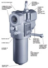
Features
- Ductile Iron Head
- Commuter Valve (To Repressurize After Element Change)
- Bleed Valve
- O-Ring Seals
- Ultipor® III Element
- Drain Port and Plug
- Optional Differential Pressure Device
- Stainless Steel Bypass Valve with Nylon Poppet (Not Shown)
- Stainless Steel Ball Valve with PTFE Seats (Not Shown)
- Change Over Handle with Latching Pin Mechanism
- All Non-Stainless Steel Parts Corrosion Protected
Maximum Acceptable Working Pressure:
6000 psi (400 bar)Fatigue Pressure Rating:
4000 psi (275 bar)Typical Burst Pressure:
24,360 psi (1680 bar)Temperature Range:
Nitrile seals -45°F to 225°F (-43°C to 107°C)Fluorocarbon seals -20°F to 250°F (-29°C to 120°C)
140°F (60°C) maximum in HWCF or water-glycol fluids
Dry Weights:
S length– 45 lbs. (21 kg)T length– 50 lbs. (23 kg)
U length– 55 lbs. (25 kg)
Filter Element Collapse Pressure:
9600– 290 psid (20 bar)Dimensional Drawings
| Figure 1. Housing Pressure Drop using fluid with 0.9 S.G. Housing Pressure drop is directly proportional to specific gravity. |
 |
| Figure 2. Bypass Valve Pressure Drop using fluid with 0.9 S.G. Bypass valve pressure drops are directly proportional to specific gravity. |
 |
Element Pressure Drop Factor
Multiply actual flow rate times factor to determine pressure drop with fluid at 150 SUS (32 cSt), 0.9 S.G.Correct for other viscosities by multiplying new viscosity in SUS/150 x new S.G/0.9.
9600 Series Element  P factor (psid/gpm) P factor (psid/gpm) | |||||
| Length | KZ | KP | KN | KS | KT |
|---|---|---|---|---|---|
| 8" | 0.46 | 0.20 | 0.17 | 0.12 | 0.09 |
| 13" | 0.27 | 0.12 | 0.10 | 0.07 | 0.05 |
| 16" | 0.20 | 0.09 | 0.07 | 0.05 | 0.04 |
Housings, Vessels, or Assemblies
| Assembly P/N: | H |
| 9685 |
|
|
|
|
|
|
|
|
|
| Table1 |
| Table2 | Table3 | Table4 | Table5 | Table6 | Table7 |

| Element P/N: | HC 9600 | F |
|
|
|
|
|
|
|
|
|
| Table4 | Table5 | Table1 |
|
|
|
Note: Choose from the options in the following tables to compile the specific Product Number.
| TABLE 1: SEAL OPTIONS | |
| Code | Seals |
|---|---|
| H | Nitrile |
| Z | Fluorocarbon |
TABLE 2: PORT STYLE OPTIONS E
| TABLE 3: PORT SIZE OPTIONS | ||
| Code | Size | Style Availability |
|---|---|---|
| 20 | 1-1/4" | All |
| TABLE 4: FILTER ELEMENT OPTIONS | ||
| Code | ßx  200 200 | ßx(c)=1000 |
|---|---|---|
| KZ | <1 | 2.5 |
| KP | 3 | 5 |
| KN | 6 | 7 |
| KS | 12 | 12 |
| KT | 25 | 22 |
TABLE 5: LENGTH OPTIONS* U
* Use code in second column for element part no.
** Nominal length in inches.
TABLE 6: BYPASS VALVE OPTIONS
TABLE 7: Differential Pressure Device Options L
T
M
S
V
B
All differential pressure devices for the 9685 set at 44 psid.
We appreciate your review of this product. Please login to your account to leave a review.