


Datasheets
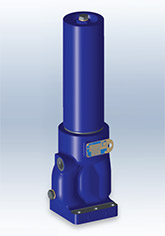
Download:Athalon™ maximum-life filters deliver the highest level of sustained fluid system protection, across all applications, regardless of severity. Featuring an industry leading BetaX(C) = 2000* filter efficiency; the highest rated filter performance available today.
(* per ISO 16889)
- Keeps fluids the cleanest, longest, for the greatest value
- Provides consistent, reliable, protection of system components over the full service life of the filter element
- Rapidly achieves and sustains required fluid system cleanliness
- Delivers maximum filter capacity in the smallest footprint
- Prevents electrostatic discharge from damaging your filter and degrading your fluid
Features
- Patented Ultipleat (laid-over pleat) filter medium pack
- Pall Stress-Resistant Technology (SRT) Media
- Coreless filter element configuration
- Low clean pressure drop for low energy operation
Notes and Specifications Filter Housing
- Flows to 230 L/min (60 US gpm)
- Pressures to 414 bar (6000 psi)
- Port Size 1¼”
- Rated Fatigue Pressure:
0-240 bar (3500 psi) per NFPA T2.06.01R2-2001 CAT C/90/*(1 million cycles), verified by testing at 0-280 bar (4050 psi) for 1 million cycles. Contact Pall for applications with higher pressures at lower cycles. - Filter Element Burst Pressure:
10 bard (150 psid) - Fluid Compatibility:
Compatible with all petroleum oils and most water glycols, water-oil emulsions, and synthetic hydraulic and lubrication fluids - Temperature Range:
Fluorocarbon Seals:
-29 ?C to 120 ?C (-20 ?F to 248 ?F)
60 ?C (140 ?F) maximum in HWCF or water glycol fluids - Bypass Valve Setting:
4.5 bard (65 psid) - Indicator Pressure Setting:
3.5 bard (50 psid) - Materials of Construction:
Head and Cover: Ductile Cast Iron Tube: Carbon steel - Filter Element :
Inorganic fibers impregnated and bonded with epoxy resins. Polymer endcaps. Anti-static media design
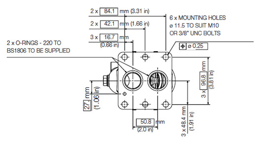
Dimensional Drawings
Dimensions in mm (inches)| Length Code | Overall length mm (in) | Cover Service Element Removal Clearance mm (in) | Head Service Element Removal Clearance mm (in) | Empty Weight kg (lb) | ||
| K | S | K | S | |||
| 04 | 358.9 (14.13) | 320.4 (12.61) | 147 (5.79) | 143 (5.63) | 12.9 (28.4) | 12.3 (27.1) |
| 08 | 460.9 (18.15) | 422.0 (16.61) | 248 (9.76) | 243 (9.57) | 14.7 (32.4) | 14.1 (31.1) |
| 13 | 595.1 (23.43) | 556.6 (21.91) | 383 (15.08) | 380 (14.96) | 17.1 (35.1) | 16.7 (36.8) |
| 20 | 765.3 (30.13) | 726.8 (28.61) | 553 (21.77) | N/A | 20.4 (45.0) | 19.8 (43.7) |
K20 OPTION SHOWN
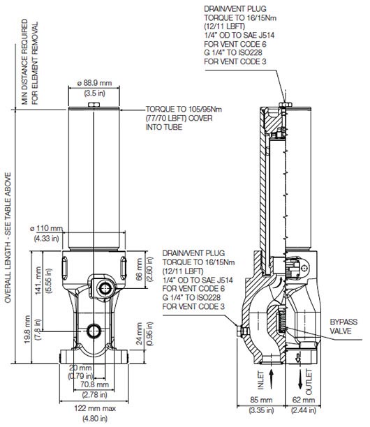
S20 OPTION SHOWN

The equipment has been assessed in accordance with the guidelines laid down in The European Pressure Directive 97/23/EC and has been classified within Sound Engineering Practice S.E.P. Suitable for use with Group 1 and 2 fluids only. Consult Sales for other fluid gas group suitability.
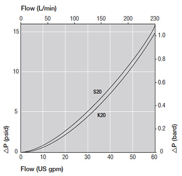
Pressure Drop Information
Housing pressure drop using fluid with 0.9 S.G.Housing pressure drop is directly proportional to specific gravity.
Element Pressure Drop
210 Series Filter Elements – bard/1000 L/min (psid/US gpm)
| Length Code | AZ | AP | AN | AS | AT |
| 04 | 20.07 (1.102) | 8.51 (0.467) | 5.72 (0.314) | 3.55 (0.195) | 2.69 (0.029) |
| 08 | 9.93 (0.545) | 4.21 (0.231) | 2.83 (0.155) | 1.76 (0.096) | 1.33 (0.073) |
| 13 | 5.95 (0.327) | 2.52 (0.139) | 1.70 (0.093) | 1.05 (0.058) | 0.80 (0.044) |
| 20 | 3.95 (0.217) | 1.68 (0.092) | 1.13 (0.062) | 0.70 (0.038) | 0.53 (0.029) |
Multiply actual flow rate times factor in table below to determine pressure drop with fluid at 32 cSt (150 SUS), 0.9 S.G. Correct for other fluids by multiplying new viscosity in cSt/32 (SUS/150) x new S.G./0.9. Note: factors are per 1000 L/min and per 1 US gpm
Sample ΔP calculation
UH210 Series 13” length housing with S20 side manifold flange using AN grade media. Operating conditions 100 L/min flow rate using a hydraulic fluid of 50 cSt and specific gravity (s.g.) 1.2.Total Filter ΔP
= ΔP housing + ΔP element
= (0.27 x 1.2/0.9) bard (housing)
+ ((100 x 1.70/1000) x 50/32 x 1.2/0.9) bard (element)
= 0.36 (housing) + 0.35 bard (element)
= 0.71 bard (10.3 psid)
Housings, Vessels, or Assemblies
For new installations, select one complete part number from each section below
Section 1 Housing P/N: UH210 [Table A] [Table B]
Note: Pall Athalon filter housings are supplied without filter elements or warning devices fitted. Never operate the filter unless a filter element is fitted and all warning device ports are sealed.
Note: Z indicates fluorocarbon seals are standard. Other options are available; contact Pall. Housing P/N designates indicator port fitted with a plastic shipping plug.
| Table A | Table B |
| Port & Length Options | Bypass & Orientation Options |
| Tables 1, 2 and 3 | Table 4 |
| K2004Z | G3 or G6 |
| K2008Z | G3 or G6 |
| K2013Z | G3 or G6 |
| K2020Z | G3 or G6 |
| S2004Z | G3, G6, G3H, or G6H |
| S2008Z | G3, G6, G3H, or G6H |
| S2013Z | G3, G6, G3H, or G6H |
| S2020Z | G3 or G6 |
Table 1: Housing Port Options
| Code | Port Style | Max. Operating Pressure |
| K | Top manifold mount | 414 bar (6000 psi) |
| S | Side manifold mount | 414 bar (6000 psi) |
Table 2: Port Size
| Code | Port Style |
| 20 | 1 1⁄4” nominal |
Table 3: Housing Length and Seal Options
| Code | Length and Seal Material |
| 04Z | 4” nominal length, fluorocarbon seals |
| 08Z | 8” nominal length, fluorocarbon seals |
| 13Z | 13” nominal length, fluorocarbon seals |
| 20Z | 20” nominal length, fluorocarbon seals |
Table 4: Bypass Valve and Service Options
| Code | Bypass Valve and Service Type |
| G3 | 4.5 bard (65 psid) bypass valve, Cap service, metric port |
| G3H | 4.5 bard (65 psid) bypass valve, Head service, metric port |
| G6 | 4.5 bard (65 psid) bypass valve, Cap service, imperial port |
| G6H | 4.5 bard (65 psid) bypass valve, Head service, imperial port |
Seal Kit P/N: SH 210 SKZ
*Other seal material options are available; Contact Pall.Section 2 Element P/N: UE 210 [Table 5] [Table 3]
Note: Z indicates fluorocarbon seals are standard.
Other options are available; contact Pall.
Table 5: Filter Element Options
| Code | ßx(c) ≥2000 based on ISO 16889 | CST Rating* |
| AZ | 3 | 07/04/01 |
| AP | 5 | 11/08/03 |
| AN | 7 | 13/09/04 |
| AS | 12 | 15/11/06 |
| AT | 25 | 16/14/08 |
* CST: Cyclic Stabilization Test to determine filter rating under stress conditions, based on SAE ARP4205
Section 3 (At least one Differential Pressure Indicator or ‘B’ type blanking plug must be ordered)
Differential Pressure Indicator P/N:
RC [Table 6] Z091 Z [Table 7]
Note: If no differential pressure indicator is selected, ‘B’ type blanking plug (P/N HC9000A104Z) must be ordered separately and fitted to replace the plastic shipping plug.
Note: Z indicates fluorocarbon seals are standard. Other options are available; contact Pall.
Table 6: Indicator Options
| Code | Brass Option indicator |
| A218M | Electrical switch (SPDT) with Hirschmann connector |
| A218R | Electrical switch (SPDT) with Hirschmann connector with Red and Green LED indicators |
| A219D | Visual indicator |
| Code | Stainless Steel indicator |
| 778NZ | Visual filter with thermal lockout |
| 861CZ | Electrical Switch (SPDT) with 6” leads |
| 861CZ* | Electrical switch (SPDT) with Hirschmann connector |
| 771BZ | Electrical switch (SPDT) with 3-pin |
Other options available; contact Pall.
* Requires YM suffix after SS code from Table 7.
Table 7: Differential Pressure Indicator Material
| Code | Pressure Setting |
| Omit | Brass Indicator |
| SS | Stainless Steel Indicator: recommended for high pressure cycle applications with pressure > 200 bar (3000 psi) |
Other setting options are available; contact Pall.
We appreciate your review of this product. Please login to your account to leave a review.