


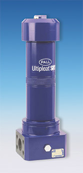
UP319 Series Ultipleat® SRT High Pressure Filters
Features
- Flows to 600 L/min (160 US gpm)
- Pressures to 250 bard (3625 psid)
- Port size 11⁄4", 11⁄2" and 2"
- Patented Ultipleat (laid-over pleat) filter medium pack
- Coreless, cageless element configuration
- Pall Stress-Resistant Technology (SRT) Media
- In-to-out filter element flow path
The UP319 Series is a Preferred Product Line utilizing Stress-Resistant Technology. Please See Ordering Information for available options
All replacement filter elements, differential pressure indicators and sealkits remain available for this series. See ‘Ordering Information’ tab above for details of spares.
Filter Housing
- Maximum Working Pressure:
250 bard (3625 psid) For high cyclic applications, use UH319 series - Typical Burst Pressure:
1050 bard (15,230 psid) - Fluid Compatibility:
Compatible with all petroleum oils, water glycols, water-oil emulsions and most synthetic hydraulic and lubrication fluids - Temperature Range:
Fluorocarbon Seals: -29 °C to 120 °C (-20 °F to 250 °F) 60 °C (140 °F) maximum in HWCF or water glycol fluids - Bypass Valve Setting:
4.5 bard (65 psid) - Indicator Pressure Setting:
3.5 bard (50 psid) - Materials of Construction:
Tube: Carbon steel
Head and Cover: Ductile Cast Iron
Filter Element
- Filter Element Burst Pressure:
10 bard (150 psid) - Ultipleat SRT Element Construction:
Inorganic fibers impregnated and bonded with epoxy resins. Polymer endcaps. Anti-static media design
The equipment has been assessed in accordance with the guidelines laid down in The European Pressure Directive 97/23/EC and has been classified within Sound Engineering Practice S.E.P. Suitable for use with Group 2 fluids only. Consult Sales for other fluid gas group suitability.
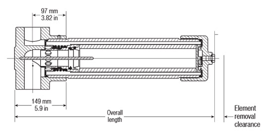
| Length Code | ‘C’ Option Overall Length mm (in.) | ‘C’ Option Element Removal Clearance mm (in.) | Empty Weight kg (lb) |
| 08 | 442 (17.4) | 205 (8.07) 138 | 29.7 (65.5) |
| 13 | 577 (22.7) | 340 (13.4) | 33.4 (73.6) |
| 20 | 747 (29.4) | 510 (20.1) | 38 (83.8) |
| 40 | 1255 (49.4) | 1020 (40.2) | 52 (114.6) |
Pressure Drop Information
Housing pressure drop using fluid with 0.9 S.G.
Housing pressure drop is directly proportional to specific gravity.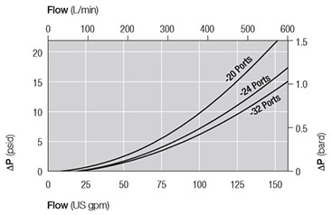
Element Pressure Drop
Multiply actual flow rate times factor in table below to determine pressure drop with fluid at 32 cSt (150 SUS), 0.9 S.G. Correct for other fluids by multiplying new viscosity in cSt/32 (SUS/150) x new S.G./0.9. Note: factors are per 1000 L/min and per 1 US gpm.319 Series Filter Elements — bard/1000 L/min (psid/US gpm)
| Length Code | AZ | AP | AN | AS | AT |
| 08 | 5.52 (0.302) | 2.30 (0.126) | 1.82 (0.100) | 1.32 (0.072) | 0.82 (0.045) |
| 13 | 3.31 (0.182) | 1.38 (0.076) | 1.09 (0.060) | 0.79 (0.043) | 0.49 (0.027) |
| 20 | 2.18 (0.120) | 0.91 (0.050) | 0.72 (0.040) | 0.52 (0.029) | 0.33 (0.018) |
| 40 | 1.10 (0.060) | 0.46 (0.025) | 0.36 (0.020) | 0.26 (0.014) | 0.16 (0.009) |
Sample ΔP calculation
UP319 Series 13" length housing with F24 (11⁄2" SAE) split flange ports using AN grade media. Operating conditions 200 L/min flow rate using a hydraulic fluid of 50 cSt and specific gravity (s.g.) 1.2.Total Filter ΔP
= ΔP housing + ΔP element
= (0.14 x 1.2/0.9) bard (housing)
+ ((200 x 1.09/1000) x 50/32 x 1.2/0.9) bard (element)
= 0.19 bard (housing) + 0.45 bard (element)
= 0.64 bard (9.3 psid)
Housings, Vessels, or Assemblies
Please select only from the following list of preferred filter housing options.
The specification of each filter housing part number is outlined in the tables below.
Seal Kit P/N: UP 319 SK Z
Note: If no differential pressure indicator is selected, 'B' type blanking plug (P/N HC9000A104Z) must be ordered separately and fitted to replace the plastic shipping plug.
Available UP319 Series Options
| UP319CA20 08ZG9 UP319CD20 08ZG9 UP319CA24 08ZG9 UP319CD24 08ZG9 UP319CC20 08ZG9 UP319CF20 08ZG9 UP319CC24 08ZG9 UP319CF24 08ZG9 UP319CA20 13ZG9 UP319CD20 13ZG9 UP319CA24 13ZG9 | UP319CD24 13ZG9 UP319CA32 13ZG9 UP319CD32 13ZG9 UP319CC20 13ZG9 UP319CF20 13ZG9 UP319CC24 13ZG9 UP319CF24 13ZG9 UP319CC32 13ZG9 UP319CF32 13ZG9 UP319CA24 20ZG9 UP319CD24 20ZG9 | UP319CA32 20ZG9 UP319CD32 20ZG9 UP319CC24 20ZG9 UP319CF24 20ZG9 UP319CC32 20ZG9 UP319CF32 20ZG9 UP319CA32 40ZG9 UP319CD32 40ZG9 UP319CC32 40ZG9 UP319CF32 40ZG9 |
The specification of each filter housing part number is outlined in the tables below.
Section 1
Housing P/N: UP 319 [Table 1] [Table 2] ++ [Table 3] ZG9Seal Kit P/N: UP 319 SK Z
Note: Pall Ultipleat SRT filter housings are supplied without filter elements or warning devices fitted. Never operate the filter unless a filter element is fitted and all warning device ports are sealed.
Note: Z indicates fluorocarbon seals are standard. Other options are available; contact Pall. The number '9' at the end of the Housing P/N designates 2 indicator ports, one fitted with a plastic shipping plug and the other with a bleed plug.
*Other seal material options are available; Contact Pall.
Table 1: Housing Orientation Options
| Code | Port |
| C | Cap service (tube up) -standard |
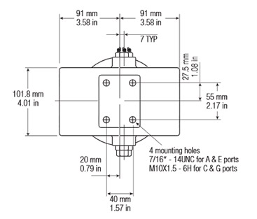
Table 2: Port Options
| Code | Port |
| A20 | 11⁄4" SAE J514 straight thread |
| D20 | 11⁄4" Flange J518C code 61 with 7/16"-14 UNC holding bolts |
| A24 | 11⁄2" SAE J514 straight thread |
| D24 | 11⁄2" Flange J518C code 61 with 1⁄2"-13 UNC holding bolts |
| A32 | 2" SAE J514 straight thread |
| D32 | 2" Flange J518C code 61 with 1⁄2"-13 UNC holding bolts |
| C20 | 11⁄4" BSP ISO 228 threads |
| F20 | 11⁄4" ISO 6162 split flange with M10 x 1.5 holding bolts |
| C24 | 11⁄2" BSP ISO 228 threads |
| F24 | 11⁄2" ISO 6162 split flange with M12 x 1.75 holding bolts |
| C32 | 2" BSP ISO 228 threads |
| F32 | 2" ISO 6162 split flange with M12 x 1.75 holding bolts |
Table 3: Housing Length Options
| Code | Length (in.)* |
| 08 | 8 |
| 13 | 13 |
| 20 | 20 |
| 40 | 40 |
* Nominal length
Section 2
Element P/N: UE 319 [Table 1] [Table 2] ZNote: Z indicates fluorocarbon seals are standard. Other options are available; contact Pall.
Table 1: Filter Element Options
| Code | ßx(c) ≥1000 based on ISO 16889 | CST Rating* |
| AZ | 3 | 08/04/01 |
| AP | 5 | 12/07/02 |
| AN | 7 | 15/11/04 |
| AS | 12 | 16/13/04 |
| AT | 22 | 17/15/08 |
* CST: Cyclic Stabilization Test to determine filter rating under stress conditions, based on SAE ARP4205
Table 2: Element Length Options
| Code | Length (in.)* |
| 08 | 8 |
| 13 | 13 |
| 20 | 20 |
| 40 | 40 |
* Nominal length
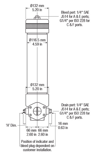
Section 3 (At least one Differential Pressure Indicator or 'B' type blanking plug must be ordered)
Differential Pressure Indicator P/N: RC [Table 1] 091 Z [Table 2] [Table 3] [Table 4]Note: Two Differential Pressure Indicators can be fitted on this housing
Note: If no differential pressure indicator is selected, 'B' type blanking plug (P/N HC9000A104Z) must be ordered separately and fitted to replace the plastic shipping plug.
Note: Z indicates fluorocarbon seals are standard. Other options are available; contact Pall.
Table 1: Differential Pressure Indicator Options*
| Code | Indicator | 'H' Dim. |
| 778NZ | 'P' type Visual indicator with thermal lockout | 21mm (0.83in.) |
| 860MZ | 'D' type Visual indicator with no thermal lockout | 21mm (0.83in.) |
| 861CZ | 'L' type Electrical switch (SPDT) with 6" leads | 38mm (1.50in.) |
| 861CZ | 'M' type Electrical switch (SPDT) with DIN43650 connector and matching cap | 78mm (3.07in.) |
| 861CZ | 'R' type Electrical switch (SPDT) and neon light indicator with DIN43650 connector and cap | 89mm (3.50in.) |
| 771BZ | 'S' type Electrical switch (SPDT) with 3-pin MS connector | 57mm (2.24in.) |
Table 2: Differential Pressure Indicator Material
| Code | Pressure Setting |
| Omit | Aluminium Alloy Indicator: use at operating pressures < 200 bard (3000 psid) |
| SS | Stainless Steel Indicator: use at operating pressures > 200 bard (3000 psid) |
* Other setting options are available; contact Pall.
Table 3: 'M' & 'R'-Type Indicator Codes*
| Code | Option |
| YM | 'M' option |
| YR | 'R' option |
* Use only if 'R' or 'M' Indicator is selected from Table 1
Table 4: 'R' Indicator Options
| Code | Option |
| 110AC | 110V AC |
| 220AC | 220V AC |
| 24DC | 24V DC |
* Use only if 'R' Indicator is selected from Table 1
We appreciate your review of this product. Please login to your account to leave a review.