Datasheets
Download:Why Use Pall ZM Coalescers:
- To remove aerosols such as hydrocarbon liquids and water which would harm the desired process gas.
- To prevent violation of strict air pollution regulations during venting.
- To prevent damage to equipment such as gas flow meters and compressors.
- To prevent fouling of catalysts.
ZM “Zero Mist” For Critical Applications
ZM coalescing filters are specifically designed for critical applications where high efficiency of aerosol removal is required. Typical applications are: compressed gas systems such as carbon dioxide, compressed air, and used upstream of gas turbines and sterile membrane filters. It effectively remove aerosols, preventing blind spots on final filters and avoiding the wetting out of final filters which can lead to liquid passing downstream
ZM coalescers collect liquid aerosols and coalesce them in to larger droplets which drain by gravity into the sump of the filter housing
Economy of Use
The superior removal efficiencies of the ZM Coalescer extend the useful life of downstream equipment, thereby reducing operating downtime and labor costs. The high area, pleated design provides single stage coalescing without the need for a separate prefiltration stage to prolong coalescer life. Finally, lower saturated pressure drop combined with single stage coalescence provides lower annual operating costs.
Features Of The Pall High Efficiency ZM Coalescing Filter
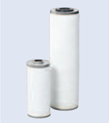
Pall coalescing filter cartridges operate economically with high separation efficiency and long life.
Positive Seal: Standard seal material is Buna-N. Viton (H) and Ethylene Propylene (J) are also available for optimum fluid compatibility.
Outer Drainage Layer: Drainage of coalesced liquid and protection from re-entrainment is provided by a polymeric outer drainage layer. This guarantees consistent, high-efficiency performance.
Metal Support Core: Axial strength and protection against liquid slugs are provided by a perforated inner support core constructed of 304 stainless steel.
Outer Cage: Media support during operation is provided by a 304 stainless steel outer support cage.
Primary Coalescer (pleated filter): The primary coalescer is a high area, pleated, epoxy coated fiberglass medium which is specially treated. It is surrounded by non-woven polymeric support and drainage layers. This provides unsurpassed separation efficiency over a wide range of flow conditions with minimum pressure drop.
304 Stainless Steel End Caps: Cartridge strength and prevention of contaminant bypass is provided by the 304 stainless steel end caps.
SFG Coalescer Element Specifications
| Model Number: | PFS1201ZM | PFS1001ZM | PFS4463ZM |
| Coalescing Efficiency at 0.3 μm | 99.99% | 99.99% | 99.99% |
| Rated Flow Air @ 100 psig (6.9 bard) and 100°F (38°C) | 400 SCFM | 200 SCFM | 60 SCFM |
| Effective Filter Area | 4.2 sq. ft. | 2.2 sq. ft. | 0.84 sq. ft. |
| Clean Pressure Drop (saturated) | 1.6 psi | 1.5 psi | 0.53 psi |
| Temperature (max.) | 140˚ F | 140˚ F | 140˚ F |
| Pressure Differential (max.)1 | 50 psi | 50 psi | 50 psi |
| Dimensions | 3 3/4” O.D. X 13 1/8 | 2 3/4” O.D. X 9 13/16” | 2 1/4” O.D. X 5 1/4” |
| Sealing Mechanism | Double open-ended with gasket seals | Double open-ended with gasket seals | Single open-ended with internal o-ring seal |
| Housing Data Sheet Reference | N/A | H1-H10 | N/A |
1 To maintain reasonable oil removal efficiencies, cartridge changeout is recommended at 8-12 psid.
ZM Performance
Coalescer performance must be measured in terms of effluent concentration and saturated pressure drop. Pall has designed the ZM Coalescer with optimized pore size and medium thickness to ensure minimum liquid penetration and high energy efficiency (low saturated pressure drop). Typical downstream aerosol concentrations, less than 0.003 ppmw, are achieved with the Pall ZM coalescer at a saturated pressure drop less than 1.6 psid per cartridge. The ZM Coalescer also has an absolute particle removal rating of 0.3 microns.
We appreciate your review of this product. Please login to your account to leave a review.


