


VFK Series Filter Housings
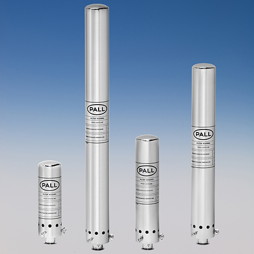
For Vent Applications
VFK Series filter housings are specifically designed for venting applications in the food and beverage industry. The in-line flow patter n of VFK housings ensures minimized pressure drop and user-friendly filter cartridge change-outs. They can be equipped with a variety of air/gas filter cartridges to address the various needs of the industry, efficiently protecting product and processes from airborne contamination.| Features | Benefits |
| Simplified design, optimized flow dynamics |
|
| Fully self-draining | Sanitary design, ease of use, satisfying standard F&B requirements |
| High quality surface finish | Enhanced cleanability |
| Simple bowl closure system | Operator-friendly handling during change-outs and maintenance |
| 316L stainless steel material | Corrosion resistance and durability |
| Variety of sizes and connection styles | Choice and convenience for easy assembly |
Materials of Construction
- Wetted parts 1.4404 (AISI 316L stainless steel)
Maximum Operating Temperature1, 2
- 120 °C (248 °F)
Surface Finish
- BE Design: < 0.4 micron Ra ( < 16 Ra microinches)
- E1 Design: < 2.0 micron Ra ( < 79 Ra microinches)
Connections3
- DIN 11851
- Clamp coupling – IDF ferrule
Filter Cartridge Compatibility4
- Pall Code 2 or Code 7 single open-end
Nominal Dimensions in mm (inches)
| Code | Cartridge height | L1 Bowl height | L2 Clearance height | L3 – Clamp coupling | L3 – DIN connection |
| 05 | 127 (5) | 280 (11.0) | 280 (11.0) | 310 (12.2) | 330 (13.0) |
| 1 | 254 (10) | 400 (15.7) | 400 (15.7) | 430 (16.9) | 400 (15.7) |
| 2 | 508 (20) | 650 (25.6) | 650 (25.6) | 680 (26.8) | 700 (27.6) |
| 3 | 762 (30) | 895 (35.2) | 895 (35.2) | 925 (36.4) | 945 (37.2) |
For specific dimensions and other connection types, please contact Pall. L1 L2
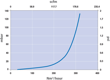
Typical Air Flow Rates / Pressure5 At Atmospheric Vent Conditions
Volume and Weight
| Weight kg (lb) | |||
| Code | Volume L (US Gal) | L2 – Clamp coupling | L2 – DIN connection |
| 05 | 1.7 (0.45) | 1.8 (3.97) | 2.5 (5.51) |
| 1 | 2.4 (0.63) | 2.2 (4.85) | 3.0 (6.61) |
| 2 | 3.8 (1.00) | 3.1 (6.83) | 3.8 (8.38) |
| 3 | 5.0 (1.32) | 3.8 (8.38) | 4.6 (10.14) |
1Maximum operating pressure and temperature ratings are vessel ratings only. Safe operation will also depend on filter element and seal use. For compatibility details, please contact Pall.
2For applications requiring in-line steam sterilization, please contact Pall for suitable housing series to use.
3For other connection types, please contact Pall.
4Refer to Pall Food and Beverage filter element literature for additional guidelines on use.
5The in-line design of the Pall VFK series vent housing ensures exceptionally low pressure drop. Pall recommends using the gas filter cartridge pressure drop when calculating the system pressure drop with maximum gas flow capacity under actual conditions. For proper vent sizing, especially in the case of pressure or vacuum-sensitive vessels, please contact Pall. Installation of appropriate rupture discs is highly recommended.
Housings, Vessels, or Assemblies
This is a guide to the part numbering structure and possible options only. For availability of specific options, please contact Pall.
Example Part Number:VFK 01 1 G7 31 BE
Part Number: VFK 01 <Table 1> G7 <Table 2> <Table 3>
Table 1: Cartridge Height
| Code | Height |
| 05 | 127 mm (5") |
| 1 | 254 mm (10") |
| 2 | 508 mm (20") |
| 3 | 762 mm (30") |
Table 2: Connection to Vessel
| Code | Description |
| 23 | Clamp coupling 1.5" – IDF |
| 31 | Clamp coupling 2.0" – IDF |
| NW50 | NW50 DIN 11851 |
Table 3: Surface Finish
| Code | Description |
| BE | <0.4 μm Ra (< 16 Ra μinches) |
| E1 | <2.0 μm Ra (< 79 Raμinches) |
Earn 10% off* your next order online by leaving a review of this product. Please login to your account to leave a review. We appreciate and value your feedback.
*Subject to Terms and Conditions.