9900/01 Series Filter Assemblies
Features
- Flows to 910 L/min (250 US gpm)
- Pressures to 420 bard (6100 psid)
- Port size 2"
- Ultipor® III filter medium pack
- Out-to-in filter element flow path
The 9900/01/04 Series is a Preferred Product Line utilizing Ultipor® III filter medium. The 9900 and 9904 Series are no longer available as standard products. See Ordering Information for the list of available 9901 Series housing part numbers.
All replacement filter elements, differential pressure indicators and sealkits remain available for this series. See 'Ordering Information' tab above for details of spares.
Maximum Acceptable Working Pressure:
6000 psi (414 bar)Fatigue Pressure Rating:
(NFPA/T2.6.1-1974 category 2/90)3000 psi (207 bar)
Typical Burst Pressure:
15,000 psi (1035 bar)Temperature Range:
Nitrile seals -45°F to 225°F (-43°C to 107°C)Fluorocarbon seals -20°F to 250°F (-29°C to 120°C)
140°F (60°C) maximum in HWCF or water-glycol fluids
Dry Weights:
X length– 134 lbs. (61.1 kg)Filter Element Collapse Pressure:
9400– 290 psid (20 bar)9901– 3000 psid (207 bar)
9404– 150 psid (10 bar)
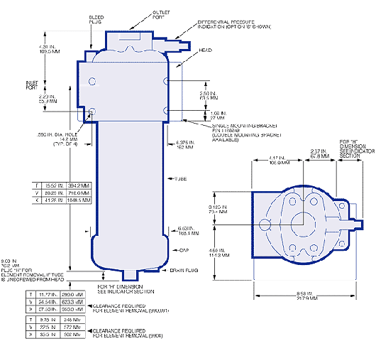
Dimensional Drawings


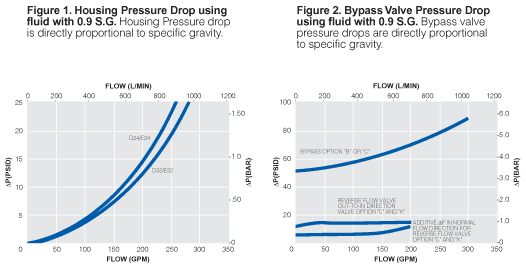
Element Pressure Drop Factor
Multiply actual flow rate times factor to determine pressure drop with fluid at 150 SUS (32 cSt), 0.9 S.G.Correct for other viscosities by multiplying new viscosity in SUS/150 x new S.G/0.9.
9400 Series Element  P factor (psid/gpm) P factor (psid/gpm) | |||||
| Length | CZ | CP | CN | CS | CT |
|---|---|---|---|---|---|
| 39" | 0.06 | 0.03 | 0.02 | 0.02 | 0.01 |
| 9901 Series Element  P factor (psid/gpm) P factor (psid/gpm) | ||
| Length | CP | CT |
|---|---|---|
| 26" | 0.10 | 0.03 |
| 39" | 0.06 | 0.02 |
Available 9900/9901 Series Options
| HZ9900D32 XB1 HZ9900E32 XB1 HZ9900F32 XB1 HZ9900G32 XB1 HZ9900G32 XC1 HZ9901E32 XW1 HZ9901E32 VW1 HZ9901G32 XW1 HZ9901G32 VW1 |
The breakdown of filter housing, replacement element and seal kit part numbers is outlined in the tables below. However, housings are only available in the part numbers listed above.
| Assembly P/N: | H |
| 990 |
|
|
|
|
|
|
| Note: For heavy duty valve (B,C,or K option) add Y128 to end of part number |
|
|
| Table1 |
| Table2 | Table3 | Table4 | Table5 | Table6 | Table7 | Table8 |
| Element P/N: | HC |
| F |
|
|
|
|
|
|
|
|
|
| Table2 | Table5 | Table6 | Table1 |
|
|
|
| TABLE 1: SEAL OPTIONS | |
| Code | Seals |
|---|---|
| H | Nitrile |
| Z | Fluorocarbon |
| TABLE 2: ELEMENT OPTIONS | ||
| Code | Element Code | Rating |
|---|---|---|
| 0 | 9400 | 290 psid (standard) |
| 1 | 9901 | 3000 psid (high collapse) |
| TABLE 3: PORT STYLE OPTIONS | |
| Code | Port Style |
|---|---|
| D | Flange SAE J518c-Code 61 |
| E | Flange SAE J518c-Code 62 |
| F | ISO 6162 Split Flange (3000 psi) |
| G | ISO 6162 Split Flange (6000 psi) |
| TABLE 4: PORT SIZE OPTIONS | |
| Code | Size |
|---|---|
| 32 | 2" |
| TABLE 5: FILTER ELEMENT OPTIONS | ||
| Code | ßx  200 200 | ßx(c)=1000 |
|---|---|---|
| CZ | <1 | 2.5 |
| CP | 3 | 5 |
| CN | 6 | 7 |
| CS | 12 | 12 |
| CT | 25 | 22 |
| CP* | 3 | 5 |
| CT* | 17 | 15 |
*9901 only. | ||
| TABLE 6: LENGTH OPTIONS* | |
| Assembly Code | Element Code** |
|---|---|
| N/A | 13 |
| V | 26 |
| X | 39 |
* Use code in second column for element part no. | |
| TABLE 7: BYPASS VALVE OPTIONS | |
| Code | Description |
|---|---|
| B | 50 psid- 9900/04 only |
| C | 50 psid bypass with Reverse Flow-9900/04 only |
| W | Non-bypass-9901 only |
TABLE 8: DIFFERENTIAL PRESSURE DEVICE OPTIONS
Differential Pressure Indicator P/N: RC [Table 8A] Z 091 Z [Table 8B]
Note: If no differential pressure indicator is selected, 'B' type blanking plug (P/N HC9000A104Z) must be ordered separately and fitted to replace the plastic shipping plug.
Note: Z indicates fluorocarbon seals are standard. Other options are available; contact Pall.
| TABLE 8A: Indicator Options For applications with operating conditions less than 200 bar (3000 psi) | |
| Code | Brass Option indicator |
|---|---|
| A218M | Electrical switch (SPDT) with Hirschmann connector |
| A218R | Electrical switch (SPDT) with Hirschmann connector with Red and Green LED indicators |
| A219D | Visual indicator |
For applications with operating conditions greater than 200 bar (3000 psi) | |
| Code | Stainless Steel indicator |
|---|---|
| 778NZ | Visual filter with thermal lockout |
| 861CZ | Electrical Switch (SPDT) with 6" leads |
| 861CZ* | Electrical switch (SPDT) with Hirschmann connector |
| 771BZ | Electrical switch (SPDT) with 3-pin |
Other options available; contact Pall. | |
| TABLE 8B: Differential Pressure Indicator Material | |
| Code | Pressure Setting |
|---|---|
| Omit | Brass Indicator: use at operating pressures < 200 bar (3000 psi) |
| SS | Stainless Steel Indicator: recommended for high pressure cycle applications with pressures > 200 bar (3000 psi) |
Other setting options are available; contact Pall. | |
Earn 10% off* your next order online by leaving a review of this product. Please login to your account to leave a review. We appreciate and value your feedback.
*Subject to Terms and Conditions.


