


Flows to 300 gpm (1135 L/min)
Pressures to 250 psi (17 bar)
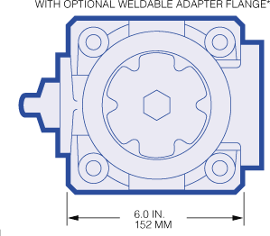
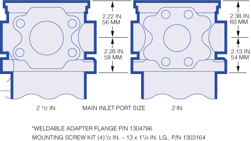
Port sizes: 2" and 2-1/2"
Please Note:
The 6500 series filter assemblies are no longer available and are being replaced with Ultipleat® UT319 Filter Assemblies
All replacement filter elements, differential pressure indicators and sealkits remain available for this series. See 'Ordering Information' tab above for details of spares.
Pressures to 250 psi (17 bar)
Port sizes: 2" and 2-1/2"
The 6500 series filter assemblies are no longer available and are being replaced with Ultipleat® UT319 Filter Assemblies
All replacement filter elements, differential pressure indicators and sealkits remain available for this series. See 'Ordering Information' tab above for details of spares.
Maximum Allowable Working Pressure:
250 psi (17 bar)Fatigue Pressure Rating:
Rated Fatigue pressure: 250 psi (17 bar) 107 cycles per NFPA T2.6.1 - 1974Temperature Range:
Nitrile seals -45°F to 225°F (-43°C to 107°C)Fluorocarbon seals -20°F to 250°F (-29°C to 120°C)
140°F (60°C) maximum in HWCF or water-glycol fluids
Dry Weights:
T length– 26.0 lbs. (11.8 kg)U length– 30.0 lbs. (13.6 kg)
V length– 35.5 lbs. (16.1 kg)
Filter Element Collapse Pressure:
150 psid (10 bar)Caution:
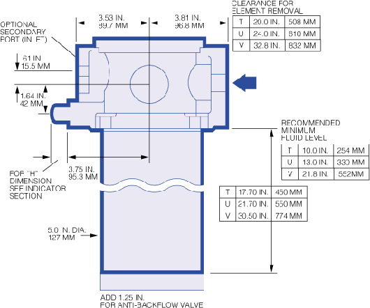
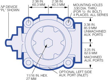
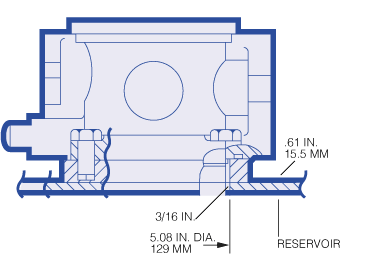
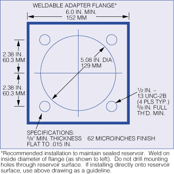
120 psi (8 bar) maximum for non-bypass valve options (prevents possible filter element collapse)Dimensional Drawings
| Figure 1. Housing Pressure Drop using fluid with 0.9 S.G. Housing Pressure drop is directly proportional to specific gravity. |
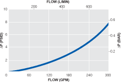 |
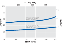
| Figure 2. Bypass Valve Pressure Drop using fluid with 0.9 S.G. Bypass valve pressure drops are directly proportional to specific gravity. |
 |
Element Pressure Drop Factor
Multiply actual flow rate times factor to determine pressure drop with fluid at 150 SUS (32 cSt), 0.9 S.G.Correct for other viscosities by multiplying new viscosity in SUS/150 x new S.G/0.9.
6500 Series Element  P factor (psid/gpm) P factor (psid/gpm) | |||||
| Length | DP | DN | DS | DT | |
|---|---|---|---|---|---|
| 13" | 0.14 | 0.08 | 0.06 | 0.05 | |
| 16" | 0.11 | 0.06 | 0.04 | 0.04 | |
| 26" | 0.08 | 0.04 | 0.03 | 0.02 | |
| |||||
Housings, Vessels, or Assemblies
| Assembly P/N: | H |
| 6500 |
|
|
|
|
|
|
|
|
|
|
| Table1 |
| Table2 | Table3 | Table4 | Table5 | Table6 | Table7 | Table8 | Table9 |

| Element P/N: | HC | 6500F |
|
|
|
|
|
|
|
|
|
|
| Table4 | Table5 | Table1 |
|
|
|
Note: Choose from the options in the following tables to compile the specific Product Number.
| TABLE 1: SEAL OPTIONS | |
| Code | Seals |
|---|---|
| H | Nitrile |
| Z | Fluorocarbon |
| TABLE 2: PORT STYLE OPTIONS | |
| Code | Port Style |
|---|---|
| A | SAE J514 straight thread |
| B | NPT |
| D | Flange SAE J518c-Code 61 |
| TABLE 3: INLET PORT SIZE OPTIONS | |
| Code | Size |
|---|---|
| 32 | 2" |
| 40 | 2-1/2" |
| TABLE 4: FILTER ELEMENT OPTIONS | ||
| Code | ßx  200 200 | ßx(c)=1000 |
|---|---|---|
| DP | 3 | 5 |
| DN | 6 | 7 |
| DS | 12 | 12 |
| DT | 25 | 22 |
| TABLE 5: LENGTH OPTIONS* | |
| Assembly Code | Element Code** |
|---|---|
| T | 13 |
| U | 16 |
| V | 26 |
* Use code in second column for element part no. | |
| TABLE 6: BYPASS VALVE OPTIONS | |
| Code | Description |
|---|---|
| A | 25 psid |
| B | 50 psid |
| W | Non-bypass |
| 8 | 25 psid with ABFV* |
| 9 | 50 psid with ABFV |
| V | Non-bypass with ABFV |
* ABFV- Anti-backflow valve. | |
| TABLE 7: DIFFERENTIAL PRESSURE DEVICE OPTIONS | |
| Code | Description |
|---|---|
| PM | Visual indicator with thermal lockout |
| DM | Visual indicator with no thermal lockout |
| LL | Electrical switch (SPDT) with 6" leads |
| TL | Electrical switch with DIN connector |
| ML | 'TL' type switch with matching wiring cap |
| SL | Electrical switch with MS receptacle |
| BL | Plug in place of indicator |
| PL | Same as PM but with plastic body |
| DL | Same as DM but with plastic body |
16 psid with "A"and "8" bypass valve 35 psid with "W," "V," "B," and "9" option. | |
| TABLE 8: SECONDARY PORT OPTIONS | ||
| Code | Port Option | Port Size |
|---|---|---|
| S | Port machined | 1-1/2" |
| N | Non-machined | - |
| Port opposite main inlet in style consistent with main inlet port (see Table 2). | ||
| TABLE 9: AUXILIARY PORT OPTIONS | ||
| Code | Port Option | Port Size |
|---|---|---|
| R | Right side* | 1-1/4" |
| L | Left side* | 1-1/4" |
| B | Both | 1-1/4" |
| N | Non-machined | - |
* Left or right side when facing inlet port. Port style consistent with main inlet port (See Table 2). | ||
Earn 10% off* your next order online by leaving a review of this product. Please login to your account to leave a review. We appreciate and value your feedback.
*Subject to Terms and Conditions.